RGB Led Strip controlled by an Arduino
I bought a few weeks ago some quite cheap 5 meters RGB LED strips (60 LEDs per meter) on eBay. My intent is to drive them with a custom Arduino receiving commands over some XBees.
I was in need of MOSFETs in order to drive the 3 RGB channels, and again found some cheap ones on eBay I received a few days ago.
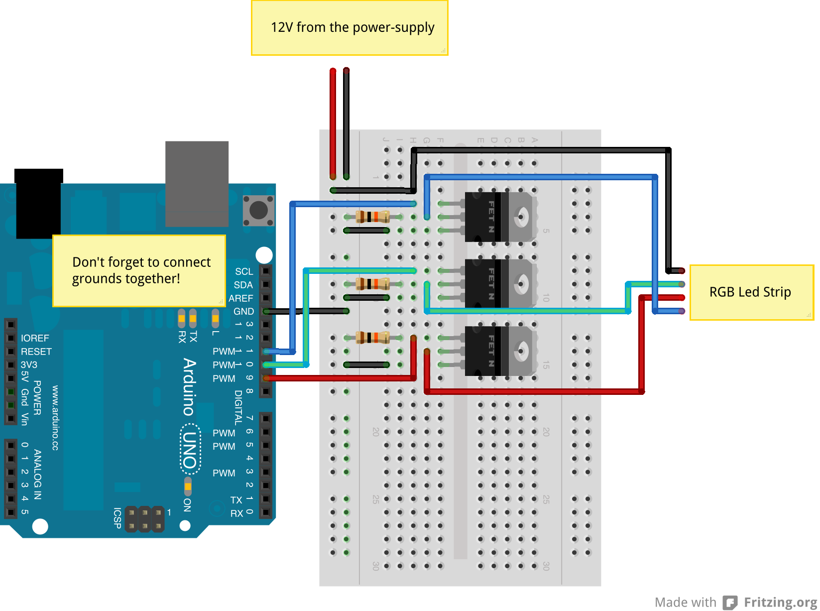
Today was a good opportunity for doing some basic tests. My first step was to control the color of the RGB LED Strip with the help of the MOSFETs and an Arduino.
Before your read the rest of this blog post, you should read Adafruit tutorial on RGB LED Strips and Bildr tutorial on MOSFETs.
I mostly did what Adafruit tutorial explains, except I added 10kΩ resistors, between each control/gate pins and ground (so 3 resistors for a RGB strip), in order to force the signal to LOW until the Arduino kicks in!
Controlling the LEDs via RGB colors, like the Adafruit example, is nice, but when you want smoother color transitions HSV or HSL (hue, saturation and lightness) is a better way to do it. Usually you keep the same saturation and lightness and only change hue.
Here is an interesting example illustrating this:
Controlling the light based on temperature
In my project, I actually want an Arduino to control the color based on the temperature of the room. In order to do so, I’m simply using 1-Wire DS18B20 sensors.
Here is the updated breadboard view:
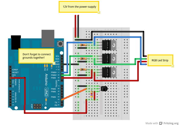
The idea is that cold temperature will tend to be blue, while a hot temperature will get a red color. If you have a look at the HSV wheel, the color will be between 240° when cold and 0° when hot, moving clock-wise (going through cyan, green and yellow).
Cold is in this case set to 18°C while hot is set to 30°C. Temperature under cold threshold will be considered as cold. Temperature above hot threshold will be considered as hot.
The final code is actually rather simple when you’ve got the HSV code already running:
Finally here is a demo of this sketch in action: