BeagleBone: Serial Ports and XBees
I bought a few months ago a BeagleBone. I wanted to experiment using it those last days in order to get some XBee data from my previous Stalker project.
Having a bit of experience with Arduino and Stalker did not help much. The BeagleBone is a complete embedded Linux system and you can’t expect to use it as easily as an Arduino (although the NodeJS demo is really cool – programming via the web browser instead of uploading programs).
Simple things like using the UART (the BeagleBone has 6 UARTs, but only 4 of them available for your programs) did turn out to be a PITA. Hopefully I could find some interesting blog posts explaining how to set them up.
So in this blog post, I will try to explain how to set up properly UART1 and UART2, and then how to connect an XBee to UART2 (there is way more information available on the Internet on how to use UART1, hence my choice to illustrate UART2 usage) in order to receive the data sent by my Stalker.
Understand BeagleBone Pins
BeagleBone pins can work in different modes (there can be up to 8 different modes for a pin). The way to tell the OS how you want to use a pin is called muxing.
Usually the first thing you need to do is to locate the UART pins you want to use.
The BeagleBone System Reference Manual is the place where we can find such information. The relevant section is 7.13 Expansion Headers.
From there we first need to figure out which pin to use (see tables 8 and 11). And then we need to figure out in which mode the pin has to be used. This can be seen in the tables 9 and 10 for expansion header P8 and tables 12 and 13 for expansion header P9.
Some few notes:
- UART0: it is only used for serial debugging, actually going through the USB port next to the power supply plug – can’t be used by your programs
- UART3: it’s pins are not available on the expansion headers – can’t be easily used by your programs
- UART5: only has RX and TX pins (no CTS and RTS pins available)
In order to make this simpler, here is below a summary of all pins used by all the BeagleBone UARTs and their expected mux mode:
| UART | RX | TX | CTS | RTS |
|---|---|---|---|---|
| UART1 | Header: P9, Pin: 26, Mode: 0 | Header: P9, Pin: 24, Mode: 0 | Header: P9, Pin: 20, Mode: 0 | Header: P9, Pin: 19, Mode: 0 |
| UART2 | Header: P9, Pin: 22, Mode: 1 | Header: P9, Pin: 21, Mode: 1 | Header: P8, Pin: 37, Mode: 6 | Header: P8, Pin: 38, Mode: 6 |
| UART4 | Header: P9, Pin: 11, Mode: 6 | Header: P9, Pin: 13, Mode: 6 | Header: P8, Pin: 35, Mode: 6 | Header: P8, Pin: 33, Mode: 6 |
| UART5 | Header: P8, Pin: 38, Mode: 4 | Header: P8, Pin: 37, Mode: 4 | – | – |
Configure the UARTs
Now that we know which pins are used for each UART and the mode in which each UART pin should be set, we need to tell the OS in which mode we want to use each pin.
This is usually done by writing a byte value into specific files on the filesystem. So now we need to know which files we need to
write to. We can figure out this information in the tables 9 and 12 we looked at before in the BeagleBone System Reference Manual. The name of the file follows this rule: /sys/kernel/debug/omap_mux/mode0_name where mode0_name has to be replaced by the name of we have for mode 0.
We now need to figure out which value to write to these files. Those files not only define in which mode to use the pin, but also if it is an input or ouput pin, if we want to use a pullup or pulldown resistor. I won’t explain much this stuff as this blog post is already rather long. If you want to understand thoses values in detail, please read GigaMegaBlog post section about Serial I/O.
Again, here is below the relevant information for the UARTs that can be used in your programs:
| UART - Pin | Filesystem location | Value (hex) | Notes |
|---|---|---|---|
| UART1 - RX | /sys/kernel/debug/omapmux/uart1rxd | 20 | Mode 0 - Input |
| UART1 - TX | /sys/kernel/debug/omapmux/uart1txd | 0 | Mode 0 - Output |
| UART2 - RX | /sys/kernel/debug/omapmux/spi0sclk | 21 | Mode 1 - Input |
| UART2 - TX | /sys/kernel/debug/omapmux/spi0d0 | 1 | Mode 1 - Output |
| UART4 - RX | /sys/kernel/debug/omapmux/gpmcwait0 | 26 | Mode 6 - Input |
| UART4 - TX | /sys/kernel/debug/omapmux/gpmcwpn | 6 | Mode 6 - Output |
| UART5 - RX | /sys/kernel/debug/omapmux/lcddata9 | 24 | Mode 4 - Input |
| UART5 - TX | /sys/kernel/debug/omapmux/lcddata8 | 4 | Mode 4 - Output |
If you need to configure CTS and RTS feel free to do so as well.
Here is below a script for configuring UART1 from the SSH connection on the BeagleBone:
echo 0 > /sys/kernel/debug/omap_mux/uart1_txd
echo 20 > /sys/kernel/debug/omap_mux/uart1_rxd

echo "UART 1 (TX):"
cat /sys/kernel/debug/omap_mux/uart1_txd
echo

echo "UART 1 (RX):"
cat /sys/kernel/debug/omap_mux/uart1_rxd
echo
And the same for UART2 (it should now be obvious how to do the same for UART4 and UART5):
echo 1 > /sys/kernel/debug/omap_mux/spi0_d0
echo 21 > /sys/kernel/debug/omap_mux/spi0_sclk

echo "UART 2 (TX):"
cat /sys/kernel/debug/omap_mux/spi0_d0
echo

echo "UART 2 (RX):"
cat /sys/kernel/debug/omap_mux/spi0_sclk
echo
Connect the XBee
In order to connect the XBee to the BeagleBone, I used a XBee Explorer USB. This is clearly much more than what’s needed. A simple XBee Explorer Regulated is sufficient. Actually all you need is a way to connect the pins of the XBee to your BeagleBone. If you find a cheaper solution, feel free to do so.
First of all we need to power the XBee. The XBee expects a 3.3V source, hopefully something we easily have on the BeagleBone.
Pins 1 and 2 on expansion P9 are ground. Pins 3 and 4 are 3.3V. Connect GND and VCC to your XBee Explorer.
As soon as we connect the GND and VCC pins of the XBee, we can see that the RSSI led turns on when there are
some XBee Packets sent on the network.
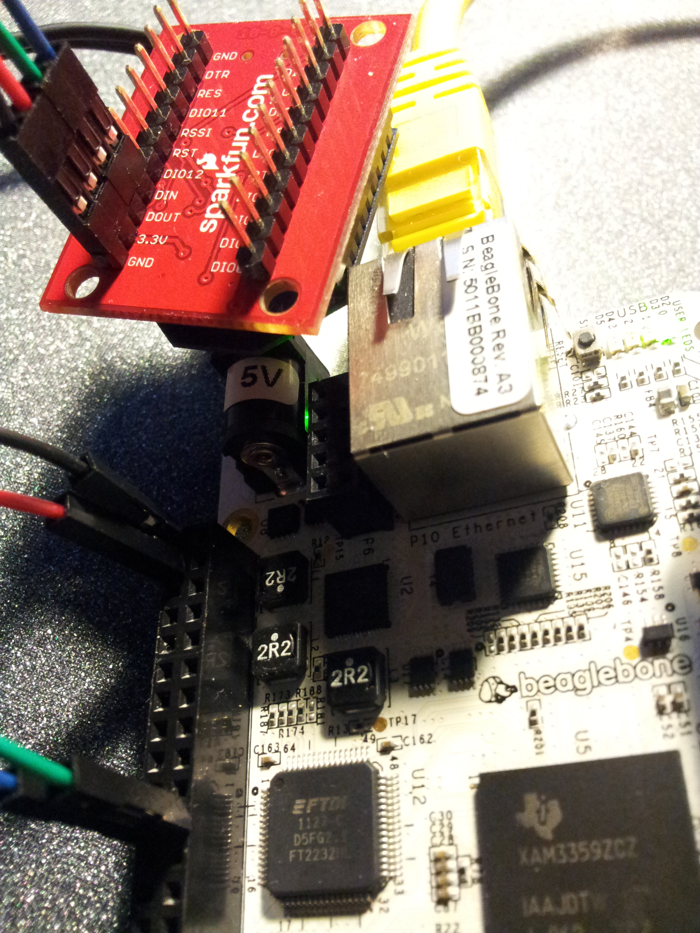
Next we need to connect UART 2 RX/TX pins of the BeagleBone to the XBee:
- UART2 TX (header P9, pin 21) should be connected to your XBee input, usually called
DIN - UART2 RX (header P9, pin 22) should be connected to your XBee output, usually called
DOUT
You should end up with something similar to this picture:
Test the connection
Now it would be nice to actually see the data received on the XBee connected to the BeagleBone.
In order to do that, we can simply run the minicom program in the BeagleBone:
minicom -b 9600 -D /dev/ttyO2
(in ttyO2 this is a O and not a zero – this is for UART2 obviously)
As soon as your XBee receives some data, it will be dumped on the console. If you plan instead to send some data to a remote XBee module, then simply write in the console. It will be sent as is to the other XBee.
More Lecture
Here are below some blog posts that helped me a lot and might interest you: